
")

")


")

Install a 7432 OR Gate Quad 2-input OR gate on the breadboard and make the (VCC) and (GND) connections. Be sure poweris off. Make the connections to the gate as shown in Figure 1. The designation 1/4 7432 means that you are using oneof the four gates that are provided by the 7432 chip. The small numbers inside the gate are the pin numbers from thechip package. Turn on the power. Set the switches as indicated in the truth table of Figure 1 and record the light con-ditions (on = 1), (off = 0) .Digital logic devices are the circuits that electronically perform
logic operations on binary variables. The binary information isrepresented by high and low voltage levels, which the deviceprocesses electronically. The devices that perform the simplest ofthe logic operations (such as AND, OR, NAND, etc.) are calledgates. For example, an AND gate electronically computes theAND of the voltage encoded binary signals appearing at its inputsand presents the voltage encoded result at its output.
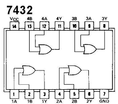
Features of 7432 ORGate
Breadboard with jumper wires
• 5 volt Power Supply
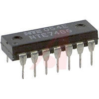
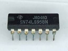
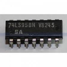
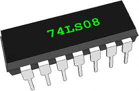
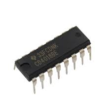
• IC chips: 7400, 7402, 7404, 7408, 7432, 7486
• Digital Module
• CircuitMaker software simulation package
• Logic Probe
1. To become familiar with the characteristics for the NOT, AND, OR, NAND,
NOR, and XOR gates
2. To wire and test the Integrated Circuit, IC, for each of the basic gates
3. To create and verify the truth table for each of the basic gates
4. To write the correct Boolean expression for each of the basic gates

Reviews
There are no reviews yet.