

Product Description:
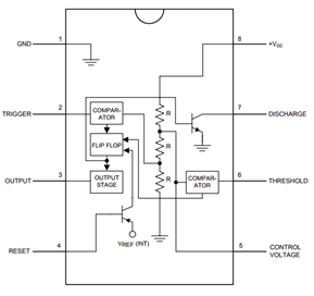
This is a common NE555 Timer/oscillator from TI. A classic for all of those first year circuits projects where you need to blink an LED, generate tone, and thousands of other great beginning projects. Google around for a huge list of resources and example projects.This IC provides a highly accurate 555 Timer circuit that is capable of producing both time delays or oscillation. It is in a single 8 pin DIL package and can be operated in astable or monostable mode with external (RC) timing control.The 555 timer is a simple circuit. By taking the trigger signal from high to low the flip-flop is set. This causes the output to go high and the discharge pin to be released from GND (0V). The releasing of the discharge pin from GND causes an external capacitor to begin charging. When the capacitor is charged the voltage across it increases. This results in the voltage on the threshold pin increasing. When this is high enough it will result in the flip-flop to resetting. This causes the output to go low and the discharge pin is also taken back to GND. This discharges the external capacitor ready for the next time the device is triggered.
This Module can easily be used with any suitable device like Arduino and other micro controller.
Pin Configuration
|
Pin Number |
Pin Name |
Description |
|
1 |
Ground |
Ground Reference Voltage 0V |
|
2 |
Trigger |
Responsible for transition of the flip-flop from set to reset. The output of the timer depends 2 I on the amplitude of the external trigger pulse applied to this pin |
|
3 |
Output |
This pin is normally connected to load as it is the only pin with output driven waveform |
|
4 |
Reset |
Negative pulse applied to this pin to disable or reset the timer. When not used for reset 4 I purposes, it should be connected to VCC to avoid false triggering |
|
5 |
Control |
Controls the threshold and trigger levels. It determines the pulse width of the output 5 Voltage I waveform. An external voltage applied to this pin can also be used to modulate the output waveform |
|
6 |
Threshold |
Compares the voltage applied to the terminal with a reference voltage of 2/3 Vcc. The 6 I amplitude of voltage applied to this terminal is responsible for the set state of the flip-flop |
|
7 |
Discharge |
Open collector output which discharges a capacitor between intervals (in phase with output). 7 I It toggles the output from high to low when voltage reaches 2/3 of the supply voltage |
|
8 |
Vcc |
Supply Voltage (Typical = 5V, Maximum = 18V) |
555 Timer IC Features
- Typical operating voltage is +5V, can withstand a maximum of +18V.
- The source/sink current of the output pin is 200mA
- Consumes up to 3mA when operating at +5V
- Trigger Voltage is 1.67 when operating at +5V
- Operating Temperature is 70 degree Celsius.
- Available in 8-pin PDIP, SOIC, and VSSOP packages
Applications
- Time Delay Generation
- Pulse Width Modulation
- Pulse generation
- Precision Timing
- Sequential Timing circuits
Reviews
There are no reviews yet.