


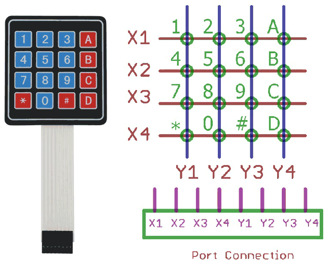
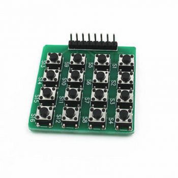
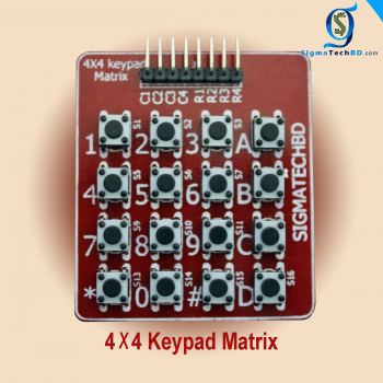
A Matrix Key Pad -4 X 4 keypad requiring eight Input/Output ports for interfacing isused as an example. Rows are connected to Peripheral Input/Output (PIO) pins configured as output. Columns are connected to PIO pins configured as input with interrupts. In this configuration, four pull-up resistors must be added in order to apply a high level on the corresponding input pins.16-Button Numeric Keypad Matrix Rubber-domes beneath each button provide satisfying key travel with each button press. Each key is emblazoned with a legible white character molded into its surface.Four mounting holes allow solid and easy mounting to a panel. The single-row 0.1-inch-pitch solder pads are breadboard friendly. Only eight of the ten solder pads carry signals – the solder pads on the ends of the row are purely for mechanical attachment. The keys are connected in a 4×4 matrix configuration.The overall dimensions of the keypad are 68.6mm tall (including the pcb header extension on the bottom) x 66mm wide. It will fit into a 60mm x 60mm square cutout in a panel. The mounting holes located in each corner are 61mm apart.
This is a great way to experiment with matrix decoding on the Arduino.
Application Ideas:
- Security systems
- Menu selection
- Data entry for embedded systemsKey Features:
- Ultra-thin design & adhesive backing provides easy integration to any project
- Easy communication with any microcontroller
- Cable included
Key Features:
- Ultra-thin design & adhesive backing provides easy integration to any project
- Easy communication with any microcontroller
- Cable included
- Security systems
- Menu selection
- Data entry for embedded systems
You can buy more component as like
Solder Lead Mini
DC Motor 9V

Reviews
There are no reviews yet.