
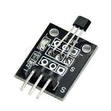
This Analog hall module strength of the field is given by an analog voltage at the signal pin of the module. The sensor must be connected to GND and 5V of the Arduino board. The output voltage is measured by analog pin A5 on the Arduino board.The example program measures the output voltage of the sensor and presents the measured value in the serial monitor of the Arduino. The LED on the board flashes at a speed dependent on the strength of the magnetic field. This can be demonstrated with a small magnet.Electricity carried through a conductor will produce a magnetic field that varies with current, and a Hall sensor can be used to measure the current without interrupting the circuit. Hall sensors can be categorized into Linear hall sensor and switch Hall sensors.A switch Hall sensor consists of voltage regulator, Hall element, differential amplifier, Schmitt trigger, and output terminal and it outputs digital values.
Features of Analog hall module
- Signals are output as long as there is a conductor cutting the magnet field.
- High precision and good linearity
- Adjustable sensitivity (accurate adjustment)
- Working voltage: 5V,PCB size: 2.3 x 2.3 cm
- Analog magnetic sensor module and a digital interface
- Built-in 13 LED build a simple circuit to produce a magnetic flash
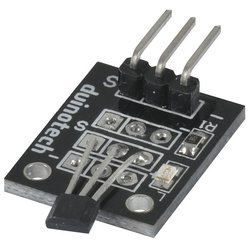
- Black PCB board, made of flame retardant epoxy resin material.
2) High precision and good linearity , Adjustable sensitivity (accurate adjustment).With no contact, abrasion, shaking, or bound
3) Working voltage: 5V;PCB size: 2.0 x 2.0 cm
4) With power light and signal output indicator
5) Output digital signals, with a 3-pin anti-reverse cable included.


Reviews
There are no reviews yet.