


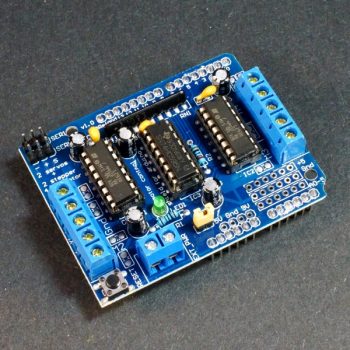
The L298N Stepper Motor Driver Board Module For Arduino/Raspberry-pi/Robotics, using ST L298 chip can directly drive two DC motor, and provides a 5V output interface, support 5v and 3.3V MCU control, you can easily control the DC motor speed and direction, you can also control the 2-phase stepper motor. Smart car essential.
The driver can control both motor RPM and direction of rotation. The RPM is controlled using PWM input to ENA or ENB pins, while of rotation direction is controlled by supplying high and low signal to EN1-EN2 for the first motor or EN3-EN4 for second motor. This Dual H-Bridge driver is capable of driving voltages up to 46V.
L298N Stepper Motor Driver
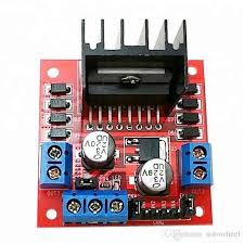
First we’ll run through the connections, then explain how to control DC motors then a stepper motor. At this point, review the connections on the L298N H-bridge module.
Consider the image – match the numbers against the list below the image:
- DC motor 1 “+” or stepper motor A+
- DC motor 1 “-” or stepper motor A-
- 12V jumper – remove this if using a supply voltage greater than 12V DC. This enables power to the onboard 5V regulator
- Connect your motor supply voltage here, maximum of 35V DC. Remove 12V jumper if >12V DC
- GND
- 5V output if 12V jumper in place, ideal for powering your Arduino (etc)
- DC motor 1 enable jumper. Leave this in place when using a stepper motor. Connect to PWM output for DC motor speed control.
- IN1
- IN2
- IN3
- IN4
- DC motor 2 enable jumper. Leave this in place when using a stepper motor. Connect to PWM output for DC motor speed control
- DC motor 2 “+” or stepper motor B+
- DC motor 2 “-” or stepper motor B-
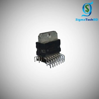
L298N Stepper Motor Driver Pinout:
The L298 comes in several different packages, the pinout for the L298N (Multiwatt15) is given below:

| no. | Name | Function | ||||||||||||||||||||||||||||||
|---|---|---|---|---|---|---|---|---|---|---|---|---|---|---|---|---|---|---|---|---|---|---|---|---|---|---|---|---|---|---|---|---|
| 1, 15 | Sense A, Sense B | The sense resistor needs to be connected between this pin and GND (not used on breakout board). | ||||||||||||||||||||||||||||||
| 2, 3 | Out 1, Out2 | Outputs of the Bridge A; the current that flows through the load connected between these two pins is monitored at pin 1. | ||||||||||||||||||||||||||||||
| 4 | Vs | Supply Voltage for the Power Output Stages | ||||||||||||||||||||||||||||||
| 5, 7 | Input 1, Input 2 | TTL Compatible Inputs of Bridge A | ||||||||||||||||||||||||||||||
| 6, 11 | Enable A, Enable B | TTL Compatible Enable Input: the LOW state disables the bridge A (enable A) and/or the bridge B (enable B). | ||||||||||||||||||||||||||||||
| 8 | GND | Ground | ||||||||||||||||||||||||||||||
| 9 | VSS | Supply Voltage for the Logic Blocks. | ||||||||||||||||||||||||||||||
| 10, 12 | Input 3, Input 4 | TTL Compatible Inputs of the Bridge B. | ||||||||||||||||||||||||||||||
| 13, 14 | Out 3, Out4 | Outputs of the Bridge B; the current that flows through the load connected between these two pins is monitored at pin 15.
|
L298N Stepper Motor Driver Features:-
- Driver chip: L298 dual H-bridge driver chip.
- Terminal driver part of the supply area VMS: +5 V ~ +35 V.
- Drive part of the peak current Io: 2A / Bridge.
- Logical part of the terminal power supply range Vss :4.5-5.5 V.
- Logical part of the operating current range: 0 ~ 36mA.
- The control signal input voltage range: 4.5-5.5V low 0V high.
- Maximum power consumption: 20W.
- Storage temperature: -25 ~ +130.
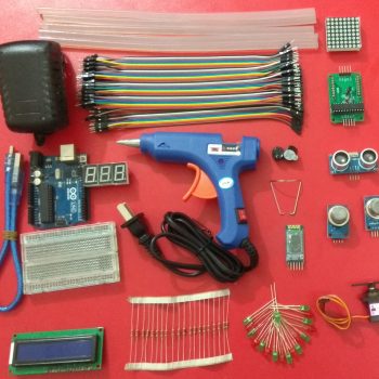
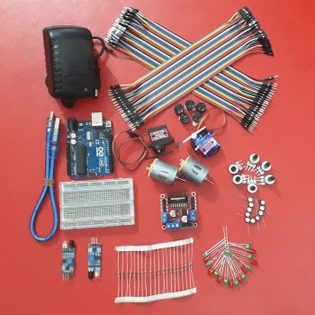
You can buy more components as like
Do You want to get industrial electrical, electronics, robotics and PLC Course?
Visit: SIATBD.COM
Online course: SIGMATECHPATHSHALA.COM


Reviews
There are no reviews yet.