
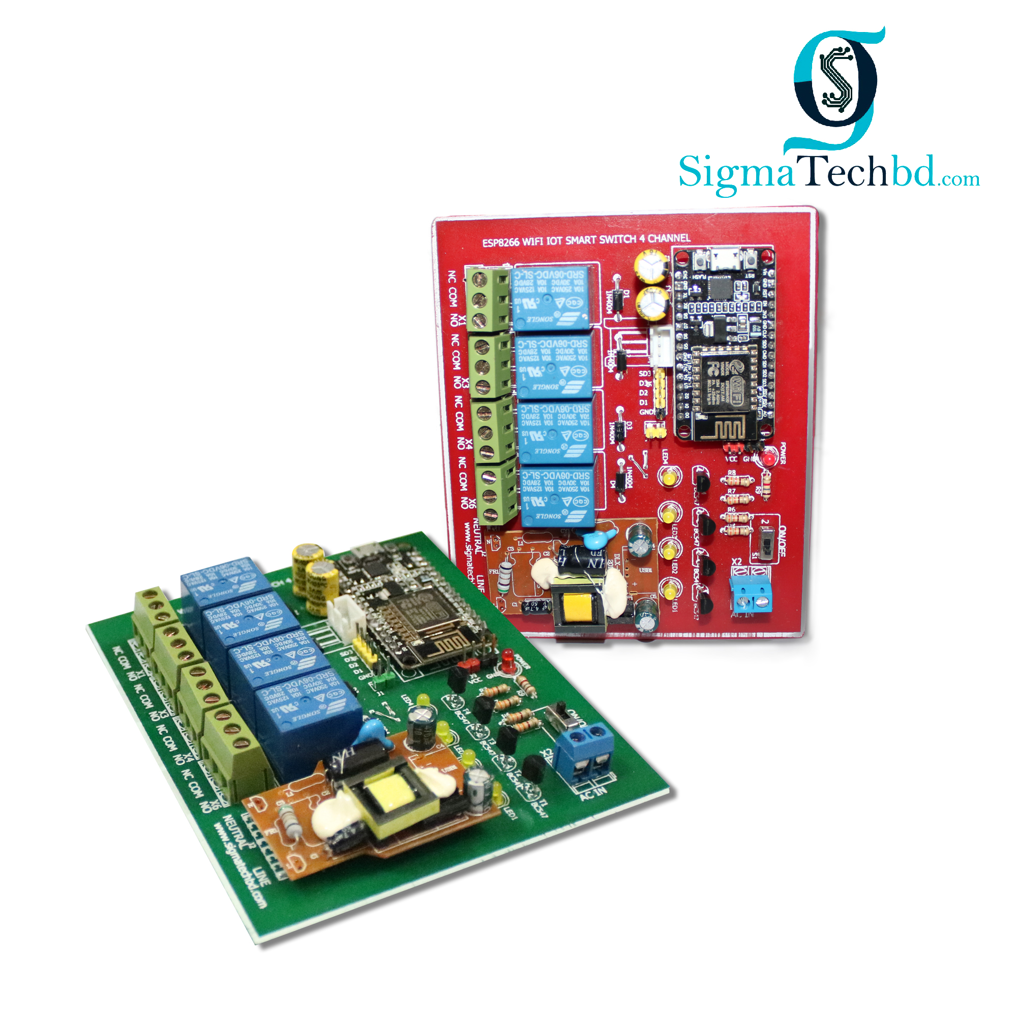
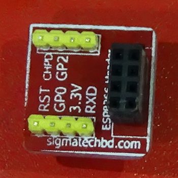
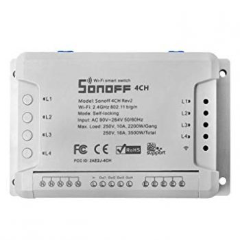
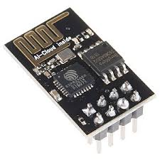
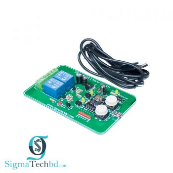
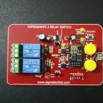
The ESP8266 WiFi 4 Channel IoT Smart Switch Onboard the ESP8266 WIFI module hthreeworkmodes:STA(client),AP(Hotspot), the STA+Ap(Hotspot+client),according to the workings of a module to the corresponding choice of WIFI module working mode.Module need before use serial debugging software and USB to TTL module send serial command was carried out on the WIFI module configuration (don’t power outages after configuration is complete,ahe RX,TX,and GND pins of the USB-to-TTL module are connected to the TX,RX,and GND pins of the module, and the IN+ ans some of the parameters of WIFI module cannot be saved when the power is cut off),Td IN- are connected to the 5V power supply.mobile phone and WIFI module after establishing a network connection can use the phone APP control relay. When cell phone equipped with WiFi module sends commands in the following order:(The default baud rate 115200 or 9600. But you should send AT + CIOBAUD = 9600 and set the baud rate as 9600 when you use a cell phone to control the relay.


Reviews
There are no reviews yet.